CEION and Electrical Resistance (ER) Monitoring
4. CEION and ELECTRICAL RESISTANCE (ER) MONITORING
4.1 INTRODUCTION
The CORMON CEION and ER systems are based on the fundamental concept that the action of corrosion on an exposed metal element will reduce the cross sectional area of the element, thereby increasing its electrical resistance. The value of the resistance increases in a predictable manner with depth of corrosion, thereby permitting the accurate determination of the metal loss occurring.
Measurements are made by comparing the resistance of an exposed sacrificial element to that of a reference element sealed within the body of the probe. In this way, temperature compensated measurements can be made.
Portable and on-line automatic instrumentation is available to permit periodic or continuous monitoring.
4.2 THEORY OF OPERATION
The electrical resistance of an element of metal is given by
R = ρl
a
Where
ρ is the material resistivity
l is its length
and a is its cross sectional area.
Thus for a given length of element, the resistance varies inversely with cross sectional area.
When the thickness of the element is diminished by a uniform corrosion attack, the reduction in thickness will cause a predictable change in the resistance of the element.
4.3 CEION TECHNOLOGY
In the advanced metal loss technology CEION, Cormon has advanced the resolution of the ratiometric. The key features of the instrumentation are:
The method of excitation
The measurement of the response.
High immunity to noise
Precision analogue circuitry
Advanced digital signal processing
Temperature measurement
The high signal to noise ratio allows field detection of 1 – 2 nm loss from 0.5mm thick sensor.
The development of sensors with high repeatability forms part of the scope. As instrument resolution improved so did the ability to evaluate sensor performance. The current generation of CEION sensor designs has excellent repeatability.
In addition to achieving sensor repeatability, it is necessary to have confidence in the corrosion repeatability of the sensor element. Will the element material in two different sensors from the same batch give close corrosion rate results in an identical environment, or will small differences in the material properties lead to divergent results? The evidence from the testing was that a difference in corrosion behaviour from probe to probe was likely if key factors are not recognised and incorporated into the design. In addition, quality control in manufacture is critical.
Typically, using a standard 10 hour exposure test of two probes to a 1% solution of sodium chloride, a metal loss between 10 and 10.5 nm/hr is measured showing that variance in the corrosion susceptibility of sensor element material has been controlled.
As a result of the development and testing it is possible to demonstrate the ability to measure the loss of 1nm of material within 5 minutes.
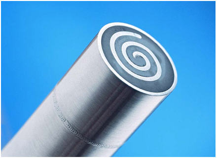
Fig. 4.1 CEION Probe Element
A number of special applications for CEION have been developed, these include Sand Erosion monitoring and the use of cooled probes to simulate condensation in operating systems.
4.4 ER – PRACTICAL APPROACH
The CORMON philosophy of ER monitoring is to use the most up-to-date electronic instrumentation to obtain measurements of the absolute resistance of the probe elements.
Whereas in older conventional style instruments a bridge circuit is used to measure the sample and reference element resistances, this new approach measures directly the absolute resistance of the elements, from which the depth of corrosion is calculated. This philosophy permits the user to offset inherent variations in probe build.
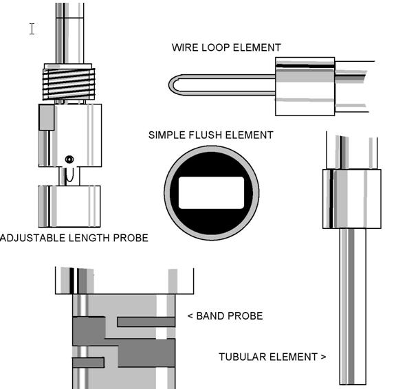
FIGURE 4.2 Examples of Electrical Resistance Probes
4.5 CORROSION MEASUREMENTS
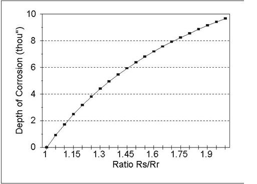
The values of the absolute resistance of the Sample (Rs) and Reference (Rr) elements are measured and the ratio Rs / Rr determined. A database calibration is used to determine the actual depth of corrosion given Rs / Rr, and from this, information on rate of corrosion may be calculated if required. The database calibration depicts how the value of Rs / Rr varies as a function of depth of corrosion. It is important to realise that each thickness and style of probe element has its own database calibration, and that accurate ER measurements can only be obtained by reference to this characteristic. A typical characteristic is shown in figure 4.1.
4.6 PROBES
ER probes are configured in several element geometries, the most common being wire loops, cylindrical tubes and flush mounted strips. Cormon have recently developed a Band probe for service in pitting corrosion situations where scaling and physical damage are possible.
Selection of the most appropriate probe and its location depends on a number of factors. Probes should be located at:
– Positions of special sensitivity where turbulence, velocity mixing, temperature of pH etc. may be of concern.
– Positions where upsets may occur i.e. after inhibitor addition, acid concentration or separation.
– Sites where abrupt changes occur such as plant metallurgy, process fluids, etc.
– Positions where from experience the highest corrosion rates would be expected.
ER probes are available in a variety of materials to suit various metallurgical applications. Probes are designed to accommodate a wide range of pressures and temperatures. Typical of the upper working limits of standard probes 6000psi and 250°C, although custom built designs may be able to extend this operation.
Process probes are available in both fixed and retrievable configurations.
(see section 7).
4.7 INSTRUMENTATION
ER probes may be monitored manually using portable equipment, automatically/continuously using single, multichannel hardwired instruments, via a computer controlled on-line system or by means of data logging equipment.
4.7.1 MANUAL INSTRUMENTS
The CORMON IER 2000 is a battery powered instrument designed to carry out field measurements of ER probes. The instrument lead couples to the in-situ probe, and a simple sequence enables quick and easy evaluation of the probe to be made.
This provides the basic technique whereby corrosion information is gathered on a periodic basis.
The IER 2000 Instrument is BASEEFA approved for operation in hazardous environments.
4.7.2. DATA LOGGING INSTRUMENTS
The cormon Data Collection Units are free standing remote data logging instruments in either ER or LPR configuration. When installed at a probe site the units make and store measurements at programmed intervals over any period. These robust, simple to use but highly efficient instruments also have an error messaging system to indicate when an acceptable measurement cannot be made – when the probe life has expired for example. The benefits of data logging include:
• Much more information achieved at moderate cost with minimum manpower
• Better quality of information and better understanding of its relation to time and process conditions.
• Ease and flexibility of operation that frees time once spent on data acquisition and handling for problem solving
AUTOMATIC MONITORING
For details of Cormon’s full range of hard-wired single and multichannel instrumentation as well as fully automatic microprocessor controlled systems, the reader is referred to the CORMON product binder.
FIGURE 4.3 Calibration characteristic for a T20 tubular element probe showing the non-linear relationship between element resistance and depth of corrosion.


